
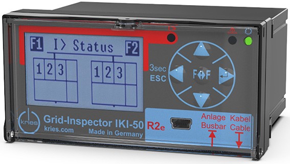
IKI-50_2F R2e
Universal fault indicator for intelligent distribution substations, 2 feeder version
Item number: 2502485
The universal fault indicator IKI-50 R2e is the appropriate solution for intelligent distribution substations and offers distribution system operators a high level of transparency and cost-effectiveness. The IKI-50 R2e includes all algorithms for selective fault detection. It is suitable for all neutral point treatments. Information on faults, load curves or limit violations is thus available on site as well as in the central network control center. Faults can be detected and localized immediately.
The IKI-50_2F R2e monitors two feeders.
Fault detection
- Directional short-circuit detection
- Directional ground short-circuit detection, directional static ground fault detection (wattmetric method), directional transient ground fault detection (wiper method), earth fault detection via pulse locating
- Suitable for all neutral point treatments
- No summing transformer required
Fault early detection
- Fault early detection by detection of transient disturbances
- Partial discharge trend detection together with CAPDIS-S2_55 (R5)
Load flow measurement
- Voltages, Currents, powers, frequencies, cos-phi, . ."
- Momentary and average values
- Limit monitoring
Network automation
- Extensive logic functions freely programmable with PC software KriesConfig
IKI-50 R2e is maintenance-free
- No battery
- Unlimited data retention
- Fault indication in case of power failure over 6 hours
Information about vulnerabilities of this product can be reported and received on this website: te.com/productsecurity.
Comparison of products
| IKI-50_2F R2e 2502485 | IKI-50_1F R2 2502352 | |
| Level of digitalisation | 1 | 2 |
| Directional short-circuit detection I>> | ✓ | ✓ |
| Directional earth short-circuit detection Ie>> | ✓ | ✓ |
| Earth fault transient detection | ✓ | ✓ |
| Pulsation detection | ✓ | ✓ |
| Directional static earth fault detection Ie>; | ✓ | ✓ |
| Slave test | ✓ | ✓ |
| Relay outputs | 4 | 6 |
| Modbus-RTU | ✓ | ✓ |
| Modbus-RTU Slave | ✓ | ✓ |
| CT-supplied | - | - |
| Auxiliary power supply | 24...230 VAC/DC (jeweils 15 %) | 24...230 VAC/DC (jeweils 15 %) |
| Buffer of power supply | Capacitor (6h) | Capacitor (6h) |
| USB interface | Mini-USB | Mini-USB |
| Digital Inputs | 4 | 6 |
| Digital Outputs | 4 | 4 |
| Digital IOs configurable | Yes | Yes |
| Switching functions feeder control unit | -- | Switching of up to two load switches 1.5-pole switching |
| Digital outputs for 1.5 pole switching | 2 | |
| Voltage inputs | 2 (LRM/CAPDIS) | 2 (1x LRM/CAPDIS, 1x precision 3.25V) |
| Voltage measurement | ✓ | ✓ |
| Precision voltage measurement | -- | Yes |
| Measuring range voltage | Capacitive | Capacitive (Input F1), Precision divider with an output signal of 3.25 V/sqrt(3) in nominal operation (input UF2) |
| Cross calibration | - | ✓ |
| Current measurement | ✓ | ✓ |
| Logic functions programmable | A total of 32 logic rules can be programmed. | A total of 32 logic rules can be programmed. |
| Balanced core CT optional | - | - |
| Stromwandlerliste für Vergleichstabelle | IKI-LUM_d92 Split-Core Transducer with cable tie (set) | Ø 92mm (2512106_H001) IKI-LUM_d92 Split-Core Transducer for C-Cone-Bushings (set) | Ø 92mm (2512106_H003) IKI-LUM_d92 Split-Core Transducer for SIEMENS-Bushings (set) | Ø 92mm (2512106_H004) | IKI-LUM_d92 Split-Core Transducer with cable tie (set) | Ø 92mm (2512106_H001) IKI-LUM_d92 Split-Core Transducer for C-Cone-Bushings (set) | Ø 92mm (2512106_H003) IKI-LUM_d92 Split-Core Transducer for SIEMENS-Bushings (set) | Ø 92mm (2512106_H004) |
| TE trend monitoring |
|
|
| Device data | |
| Article number | 2502485 |
| Product designation | IKI-50_2F R2e Universal fault indicator for intelligent distribution substations | 2 feeder version |
| Number of feeders | 2 |
| Parameterization software | KriesConfig |
| Configuration | Via software Kries-Config (download at kries.com), Via HMI and display (limited) |
| Operating elements and display | |
| Front display | LC-Display and LEDs |
| Direction keys | Operation via four direction keys |
| Red LED (1) | Error event detected | internal energy storage empty |
| Yellow LED (2) | Slave test | Primary test | Device warnings |
| Dreen LED (3) | Status message device status |
| Two feeder monitoring | ✓ |
| Buffer of power supply | Capacitor (6h) |
| Dimensions and installation instructions | |
| Case height x width x depth | 49 x 96 x 108 mm |
| Cutout height x width | 45 x 92 mm |
| Norm cutout dimensions | DIN IEC 61554:2002-08 |
| Installation type | Panel mounting |
| Sheet thickness | 1.5 ... 2.5 mm |
| Operating conditions | |
| Operating temperature | -25°C ... 55°C |
| Storage temperature | -25°C ... 70°C |
| Humidity | max. 95 % relative Feuchte bei 40° C |
| Protection class | IP54 (Front) |
| Fault detection and failure forecast | |
| Fault detection | Individually selectable, any combinations possible |
| Star point types | Short-term low-ohmic terminated neutral, Low-ohmic terminated neutral, Inductive terminated neutral, Isolated neutral |
| Short circuit detection I>> | ✓ |
| Directional short-circuit detection I>> | ✓ |
| Threshold current short-circuit detection I>> | 100 A ... 1,000 A (adjustable in steps) |
| Threshold time short-circuit detection I>> | 40 ms ... 1,600 ms (adjustable in steps) |
| Earth short-circuit detection Ie>> | ✓ |
| Directional earth short-circuit detection Ie>> | ✓ |
| Threshold current earth short-circuit detection Ie>> | 40 A ... 1,000 A (adjustable in steps) |
| Threshold time earth short-circuit detection Ie>> | 40 ms ... 1,600 ms (adjustable in steps) |
| Directional static earth fault detection Ie>; | ✓ |
| Threshold current static earth fault detection Ie> | 2 A ... 30 A (adjustable in steps) |
| Directional transient earth fault detection Ie> | ✓ |
| Threshold current transient earth fault detection 3I0 | 1 A ... 1,000 A (freely adjustable) |
| Threshold voltage transient earth fault detection 3U0 | 1 kV ... 300 kV (freely adjustable) |
| Earth fault detection via pulse locating | ✓ |
| Pulse length of pulse locating | symmetrical / asymmetrical |
| Transient fault detection IIe> | ✓ |
| TE trend monitoring |
|
| Fault reset | Auto, Manually on the device, After time (1 h ... 8 h, configurable) |
| Event log | The last 20 fault events are stored with event number, date, time, name of the triggering fault detection, fault direction, phase and fault current value. |
| Earth fault transient detection | ✓ |
| Directional earth short-circuit detection | ✓ |
| Interfaces and communication | |
| USB interface | Mini-USB |
| Modbus-RTU | ✓ |
| Modbus-RTU Slave | ✓ |
| Modbus transmission rates [kBd] | 9600, 19200, 38400, 57600, 115200 |
| Slave test | ✓ |
| Digital Inputs | 4 |
| Potential-free digital inputs | 4 |
| Digital Outputs | 4 |
| Digital IOs configurable | Yes |
| Switching functions feeder control unit | -- |
| Connection cable cross section | Max. 2,5 mm |
| Switching capacity relay | AC: max. 62,5 VA max. 2A; max. 250 VAC DC: max. 2A @ 40 VDC |
| Relay outputs | 4 |
| Voltage inputs | 2 (LRM/CAPDIS) |
| Current transformer | 6 |
| Measurement values and functions | |
| Voltage measurement | ✓ |
| Measuring range voltage | Capacitive |
| Phase-to-ground voltages | ✓ |
| Phase to phase voltages | ✓ |
| Measuring range voltage | 0.02 kV ... 92 kV | Start of voltage measuring range: 2% of Un |
| Precision voltage measurement | -- |
| Cross calibration | - |
| Current measurement | ✓ |
| Measuring range current | 0.5 A ... 1,158 A (with current transformer IKI-LUM) |
| Zero-sequence current | ✓ |
| Conductor currents | ✓ |
| Active power | ✓ |
| Reactive power | ✓ |
| Apparent power | ✓ |
| Rotary field detection | ✓ |
| Frequency measurement | ✓ |
| Mean value determination | ✓ |
| Min-max value determination | ✓ |
| Phase position | ✓ |
| Phase shift cos-phi | ✓ |
| Limit value monitoring | Voltage, current, frequency, reactive power and voltage |
| Logic functions programmable | A total of 32 logic rules can be programmed. |
| Power supply | |
| Auxiliary power supply | 24...230 VAC/DC (jeweils 15 %) |
| Power consumption | 2 W |
| Insulation voltage | 2 kV, 1 min |
| CT-supplied | - |
| Capacitor buffer | ✓ |
| Display buffer for fault indication | Unlimited data retention (independent of auxiliary power and buffer power); Error display after power failure (depending on adjustable follow-up time):
|

 IKI-LUM d92
  IKI-LUM d92


