Cookie preferences
This website uses cookies, which are necessary for the technical operation of the website and are always set. Other cookies, which increase the comfort when using this website, are used for direct advertising or to facilitate interaction with other websites and social networks, are only set with your consent.
Configuration
Technically required
These cookies are necessary for the basic functions of the shop.
"Allow all cookies" cookie
"Decline all cookies" cookie
CSRF token
Cookie preferences
Currency change
Customer recognition
Customer-specific caching
Individual prices
Selected shop
Session
Comfort functions
These cookies are used to make the shopping experience even more appealing, for example for the recognition of the visitor.
Note
Statistics & Tracking
Affiliate program
Track device being used
IKI-55
Networkable Feeder Control Units for Distribution Substations
Item number: 2502400_H003
Item number: 2502400_H003
The IKI-55 Feeder Control Unit can be used in load switchgear for directional fault detection,... more
Product information "IKI-55"
The IKI-55 Feeder Control Unit can be used in load switchgear for directional fault detection, load flow measurement, and control of load and ground switches. Likewise, a number of automation and monitoring functions are available with the IKI-55.
The IKI-55 is network-capable in its basic version and can communicate with the control station and other remote stations via various communication protocols. It can also be used as a Modbus master. The IKI-55 M is a Modbus-only variant.
The IKI-55 is designed for the connection of small-signal current transformers according to IEC 61869-10 as well as small-signal voltage transformers according to IEC 61869-11. In conjunction with a sensor adapter, conventional conversion transformers for current measurement as well as capacitive and precision dividers can be connected.
Fault detection
- Directional short-circuit detection
- Directional ground short-circuit detection
- Directional ground fault detection with static and transient fault detection
- Ground fault detection via pulse locating
- Suitable for all neutral point treatments
- No summing transformer required
- Fault recording with export as Comtrade file
Early fault detection
- Fetection of transient faults (Intermittent ground faults)
- In conjunction with a CAPDIS- S2_55 (R5): Detection of partial discharges and their frequency and trend
Load flow measurement
- Voltages, currents, powers, frequencies, cos phi
- Momentary and average values
- Cross calibration (With additional adapter)
- Phase comparison function for voltages (With additional adapter)
Comprehensive control and monitoring functions
- Control of motor controllers for switching load and ground switches
- Free programmable logic functions
- Automatic Transfer Switch (ATS)
- Limit value monitoring
Simple operation of the unit
- Additional LEDs to indicate the fault direction
- Self-explanatory operation via direction keys
Extended safety features
- User roles safety concept, password protected
- Remote firmware update via REST interface (deactivable)
- USB interface deactivable
Communication protocols
- IEC 60870-5-104 for communication with control center
- MQTT, REST for communication with databases or management systems
- Modbus RTU (Master)
Comparison of products
| IKI-55 2502400_H003 | IKI-55 M 2502400_H001 | IKI-55 PQ 2502400_H004 | |
| Level of digitalisation | 2 | 2 | 2 |
| Directional short-circuit detection I>> | ✓ | ✓ | ✓ |
| Directional earth short-circuit detection Ie>> | ✓ | ✓ | ✓ |
| Earth fault transient detection | ✓ | ✓ | ✓ |
| Pulsation detection | ✓ | ✓ | ✓ |
| Directional static earth fault detection Ie>; | ✓ | ✓ | ✓ |
| Slave test | ✓ | ✓ | ✓ |
| Modbus-RTU | ✓ | ✓ | ✓ |
| Modbus RTU Master | ✓ | - | ✓ |
| Modbus-RTU Slave | ✓ | ✓ | ✓ |
| IEC 60870-5-104 Slave | ✓ | - | ✓ |
| MQTT | ✓ | - | ✓ |
| REST API | ✓ | - | ✓ |
| LAN connection | ✓ | - | ✓ |
| Encryption of communication (LAN) | TLS | TLS | |
| CT-supplied | - | - | - |
| Auxiliary power supply | 24 VDC/AC +/-20% | 24 VDC/AC +/-20% | 24 VDC/AC +/-20% |
| USB interface | Mini-USB | Mini-USB | Mini-USB |
| PT100 input for temperature compensation of sensors | - | - | - |
| Digital Inputs | 6 | 6 | 6 |
| Digital Outputs | 6 | 6 | 6 |
| Digital IOs configurable | Yes | Yes | Yes |
| Switching functions feeder control unit | Switching of up to two load switches 1.5-pole switching | Switching of up to two load switches 1.5-pole switching | Switching of up to two load switches 1.5-pole switching |
| Digital outputs for 1.5 pole switching | 2 | 2 | 2 |
| Voltage inputs | 1 (With additional adapter 2: 2x LRM/CAPDIS or 1x LRM/CADPIS + 1x precision 3.25V) | 1 (With additional adapter 2: 2x LRM/CAPDIS or 1x LRM/CADPIS + 1x precision 3.25V) | 1 (With additional adapter 2: 2x LRM/CAPDIS or 1x LRM/CADPIS + 1x precision 3.25V) |
| Voltage measurement | ✓ | ✓ | ✓ |
| Precision voltage measurement | Yes | Yes | Yes |
| Power Quality according to DIN EN 50160 | Frequency IEC 61000-4-30 cl. 5.1 Voltage dips IEC 61000-4-30 cl. 5.4 Voltage swells IEC 61000-4-30 cl. 5.4 Voltage interruptions IEC 61000-4-30 cl. 5.5 Rapid voltage changes IEC 61000-4-30 cl. 5.11 | ||
| Current measurement | ✓ | ✓ | ✓ |
| Logic functions programmable | A total of 32 logic rules can be programmed. | A total of 32 logic rules can be programmed. | A total of 32 logic rules can be programmed. |
| Balanced core CT optional | - | - | - |
| Stromwandlerliste für Vergleichstabelle | IKI-LUM_d92 Split-Core Transducer with cable tie (set) | Ø 92mm (2512106_H001) IKI-LUM_d92 Split-Core Transducer for C-Cone-Bushings (set) | Ø 92mm (2512106_H003) IKI-LUM_d92 Split-Core Transducer for SIEMENS-Bushings (set) | Ø 92mm (2512106_H004) | IKI-LUM_d92 Split-Core Transducer with cable tie (set) | Ø 92mm (2512106_H001) IKI-LUM_d92 Split-Core Transducer for C-Cone-Bushings (set) | Ø 92mm (2512106_H003) IKI-LUM_d92 Split-Core Transducer for SIEMENS-Bushings (set) | Ø 92mm (2512106_H004) | IKI-LUM_d92 Split-Core Transducer with cable tie (set) | Ø 92mm (2512106_H001) IKI-LUM_d92 Split-Core Transducer for C-Cone-Bushings (set) | Ø 92mm (2512106_H003) IKI-LUM_d92 Split-Core Transducer for SIEMENS-Bushings (set) | Ø 92mm (2512106_H004) |
| TE trend monitoring |
|
|
|
| Device data | |
| Article number | 2502400_H003 |
| Quantity unit | Piece |
| Product designation | Grid Controller IKI-55 | Networkable Feeder Control Unit |
| Number of feeders | 1 |
| Firmware | 1.0.0 |
| Parameterization software | KriesConfig |
| Configuration | Via HMI and display (limited), Via software Kries-Config (download at kries.com) |
| Firmware update | Remote via network interface |
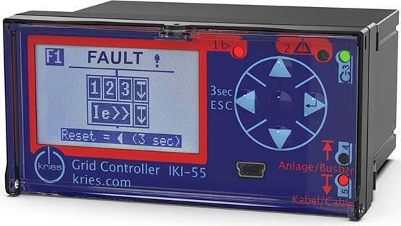
| Operating elements and display | |
| Front display | LC-Display and LEDs |
| Direction keys | 1 - 4 for navigation in menu |
| Red LED (1) | Error event detected |
| Yellow LED (2) | Device warnings |
| Dreen LED (3) | Status message device state |
| Yellow LED (4) | Fault detected in the direction of the busbar |
| Red LED (5) | Error event detected in the direction of the cable |
| Dimensions and installation instructions | |
| Case height x width x depth | 48 x 96 x 110 mm |
| Cutout height x width | 45 x 92 mm |
| Norm cutout dimensions | DIN IEC 61554:2002-08 |
| Installation type | Panel mounting |
| Operating conditions | |
| Operating temperature | -40°C ... 70°C |
| Storage temperature | -40°C ... 80°C |
| Protection class front side | IP54 |
| Protection class | IP40 / Front IP54 |
| System frequency | 50 Hz / 60 Hz (selectable) |
| Fault detection and failure forecast | |
| Fault detection | Individually selectable, any combinations possible |
| Star point types | Short-term low-ohmic terminated neutral, Low-ohmic terminated neutral, Inductive terminated neutral, Isolated neutral |
| Short circuit detection I>> | ✓ |
| Directional short-circuit detection I>> | ✓ |
| Threshold current short-circuit detection I>> | 50 A – 1,000 A |
| Threshold time short-circuit detection I>> | 40 ms – 5 s |
| Earth short-circuit detection Ie>> | ✓ |
| Directional earth short-circuit detection Ie>> | ✓ |
| Threshold current earth short-circuit detection Ie>> | 10 A – 1,000 A |
| Threshold time earth short-circuit detection Ie>> | 40 ms – 5 s |
| Directional static earth fault detection Ie>; | ✓ |
| Threshold current static earth fault detection Ie> | 2 A – 30 A |
| Threshold time static earth fault detection Ie> | 200 ms – 2 s |
| Directional transient earth fault detection Ie> | ✓ |
| Threshold current transient earth fault detection 3I0 | 1 A – 1,000 A |
| Threshold voltage transient earth fault detection 3U0 | 0.1 kV – 100 kV |
| Earth fault detection via pulse locating | ✓ |
| Pulse length of pulse locating | symmetrical / asymmetrical |
| Transient fault detection IIe> | ✓ |
| TE trend monitoring |
|
| Fault reset | Auto, Manually on the device, After time (1 h ... 8 h, configurable) |
| Reset setting | Time: 1 - 1 h; manual, auto |
| Event log | 20 events |
| Fault recorder | ✓ |
| Fault record - formats | Comtrade |
| Fault record - number | 20 |
| Fault record - recording duration | 2,5 s at 50 Hz | 2,09 s at 60 Hz |
| Fault record - Frequency | 6,4 kHz at 50 Hz | 7,68kHz at 60 Hz |
| Fault record - Pretrigger | 0,31 s at 50 Hz | 0,258 s at 60 Hz |
| Earth fault transient detection | ✓ |
| Directional earth short-circuit detection | ✓ |
| Interfaces and transmission protocols | |
| USB interface | Mini-USB |
| Transmission protocols | MQTT, REST, IEC 60870-5-104, Modbus-RTU |
| Modbus-RTU | ✓ |
| Modbus RTU Master | ✓ |
| Modbus-RTU Slave | ✓ |
| Modbus transmission rates [kBd] | 9600, 19200, 38400, 57600, 115200 |
| MQTT | ✓ |
| REST API | ✓ |
| IEC 60870-5-104 Slave | ✓ |
| Encryption of communication (LAN) | TLS |
| LAN connection | ✓ |
| Slave test | ✓ |
| Digital Inputs | 6 |
| Digital inputs - connections | Push-In, Connection of solid and stranded conductors: 0.08 to 0.5 mm² | Connection of stranded conductors with ferrule: 0.25 to 0.34 mm² |
| Digital inputs - switching thresholds | ON > 19 VDC / OFF < 10 VDC |
| Digital inputs - voltage ranges | 24 DC to 60 VDC |
| Digital inputs - current consumption | Max. 6 mA |
| Digital Outputs | 6 |
| Digital outputs for 1.5 pole switching | 2 |
| Digital outputs - connections | Push-In, Connection of solid and stranded conductors: 0.08 to 0.5 mm² | Connection of stranded conductors with ferrule: 0.25 to 0.34 mm² |
| Digital outputs - variants | Floating |
| Digital outputs - switching capacity | 1 A at 30 VDC |
| Digital outputs - dielectric strength | Max. 80V |
| Digital IOs configurable | Yes |
| Switching functions feeder control unit | Switching of up to two load switches 1.5-pole switching |
| Voltage input Input impedance | 2 MOhm, 50 pF |
| Voltage input Input range | 0,4 V – 4,1 V |
| Voltage input measurement accuracy | 1% |
| Voltage input transformation ratio | 10000:1 (settable) |
| Voltage input standard | IEC 61869-11 |
| Current input Version | Rogowski current sensor |
| Current input Input impedance | 10 MOhm, 50 pF |
| Current input Measuring range | 0,1 A up to 2000 A |
| Current input Measuring accuracy | 1%, +- 0.5 A |
| Current input Ratio | 50 A / 22,5 mV (50Hz) (settable) |
| Current input standard | IEC 61869-10 |
| PT100 input for temperature compensation of sensors | - |
| Voltage inputs | 1 (With additional adapter 2: 2x LRM/CAPDIS or 1x LRM/CADPIS + 1x precision 3.25V) |
| Measurement values and functions | |
| Voltage measurement | ✓ |
| Phase-to-ground voltages | ✓ |
| Phase to phase voltages | ✓ |
| Precision voltage measurement | Yes |
| Current measurement | ✓ |
| Active power | ✓ |
| Reactive power | ✓ |
| Apparent power | ✓ |
| Rotary field detection | ✓ |
| Frequency measurement | ✓ |
| Limit value monitoring | Parameterizable |
| Logic functions programmable | A total of 32 logic rules can be programmed. |
| Power supply | |
| Auxiliary power supply | 24 VDC/AC +/-20% |
| Power input - power consumption | 0.5 A |
| Power supply input - connections | Connection of solid and stranded conductors: 0.2 to 2.5 mm2 / Connection of stranded conductors with ferrule: 0.25 to 1.5 mm2 / Connection of stranded conductors with ferrule without plastic collar: up to 2.5 mm2 |
| CT-supplied | - |

 IKI-LUM d92
 CT for bushings, directional, for measured value acquisition, for C-cone, set
Price on request
 IKI-LUM d92
 CT for bushings, directional, for measured value acquisition, for Siemens switchgears, set
Price on request

 Small-Signal Sensor-Adapter
 To Connect CAPDIS, voltage sensors and IKI-LUM to IKI-55
Price on request